Detailed Analysis And Application Of Impeller Parts In Overall Process Design
See all aspects of life and taste the world. Before reading the article, you can move your little hands to follow and like it. This will not only increase your sense of participation, but also make it easier for you to provide valuable feedback to the editor at any time. Thanks. Support the editor!
Structural analysis of impeller parts
Integral impellers are widely used in aviation, aerospace, navigation, military industry, automobile manufacturing, air conditioning manufacturing, medical and other fields , because integral impellers are key components of precision machinery such as aerospace engines, gas turbines, turboexpanders, centrifugal refrigerators, centrifugal compressors, etc. part.
As a key component of the engine, the integral impeller has a great impact on the performance of the engine. Its processing has become a key link in improving engine performance . The overall processing quality of the impeller directly affects the quality and output efficiency of the engine. The part shown is equipped with an integral impeller. The turbine wheel or turbine blades and the compressor wheel are the main components of the turbocharger.
The simple structure of the integral impeller is shown in the figure. Mainly composed of hub and blades . The hub curved surface is obtained by rotating the streamline curve around the central rotation axis. The blade surface is achieved by stretching the blade curve along the vertical direction of the central axis and then thickening the blade body. The upper curved surface of the blade allows for cutting.
The structural blades of the integral impeller part are evenly distributed on the hub. The design of the integral impeller is based on the theory of complex spatial fluid dynamics, and its blade shape conforms to the laws of fluid flow . The shape of the blades of the integral impeller is more complex and the accuracy requirements are also higher. When programming the overall impeller, the three-dimensional model of the impeller must be installed for programming, so that the design requirements can be met, and the processed impeller can meet the performance requirements of the entire machine. The impeller is generally made of harder materials or imported materials, and must meet high-precision requirements during processing. Therefore, the processing of the integral impeller requires a high success rate and is not allowed to be scrapped to avoid wasting materials and manufacturing time. Delay .
Impeller geometry
The design mechanism of the integral impeller generally designs the blades of the impeller to be one long and one short to improve the performance of the impeller . However, programming this impeller structure is quite difficult, especially with short blades. This requires programmers to solve the problem of reasonable operation of tool paths.
The two surfaces of the impeller blades are curved but straight. These two surfaces are called the pressure surface and the suction surface respectively. The intermediate surface between two curved surfaces is the fillet transition surface. Transition fillets can use a variety of mechanisms, such as arcs, multiple small arcs, ellipses, etc., with large or small curvatures.
According to the law of fluid movement, the variable rounding rule is generally used for blade root rounding. Starting from the impeller inlet, the blade root radius changes from small to large . A smaller fillet radius is selected at the inlet to reduce clogging losses, and a larger fillet radius is used in the middle of the blade to improve the stress on the blade.
The blade surface of the integral impeller has a ruled surface that cannot be expanded, which is caused by the deformation of the curved surface. That is, the straight line directions at the intersection of the wheel hub and the wheel cover are different. When programming, using linear elements to define the tool axis can easily cause the tool to cut into the blade, that is, overcut. The integral impeller processed by this method will have certain defects. This is mainly reflected in the fact that the middle part of the blade is thinner and the middle part of the two surfaces is concave.
The software can only define tool axes along inner and outer meridian lines. The resulting deformation of the blade is inevitable. If the blade surface is severely distorted, large overcuts will occur . This is difficult for general-purpose software to handle. The solution is to use multi-segment, multi-point programming to refine the surface segments. The only disadvantage of this is that the surface quality of the machined blade is slightly affected.
Impeller parts manufacturing process analysis
Currently, the commonly used processing methods for integral impellers include milling and casting. The processing technology of casting integral impeller is generally used for the production of single-piece and small batch impellers. However, there are many defects in the casting process. Specific defects include casting inclusions, casting size uniformity, casting shape differences, casting mold manufacturing, etc. Slag inclusions can cause impeller failure. Inconsistent dimensions can lead to poor interchangeability of parts and different performance differences between different machines. The difference in shape can result in lower power output for diesel engines equipped with integral impeller components. The production and processing of molds will increase the manufacturing cost of the impeller.
Cast impeller parts are still suitable for high temperatures and harder materials. But now the development of manufacturing technology gradually adopts unified cutting processing to produce integral impellers . Especially in the processing of samples, small batches and even large batches, CNC processing has become the mainstream processing method. CNC machining makes it easy to modify part dimensions, and the manufacturing cycle is short, which can be achieved by changing the CNC program.
Currently, the commonly used processing method for integral impellers with complex shapes is to use general software programming (such as the CAM module of UHNX) to generate a program, and then use software simulation to input the five-axis linkage machining center machine tool for processing.
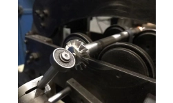
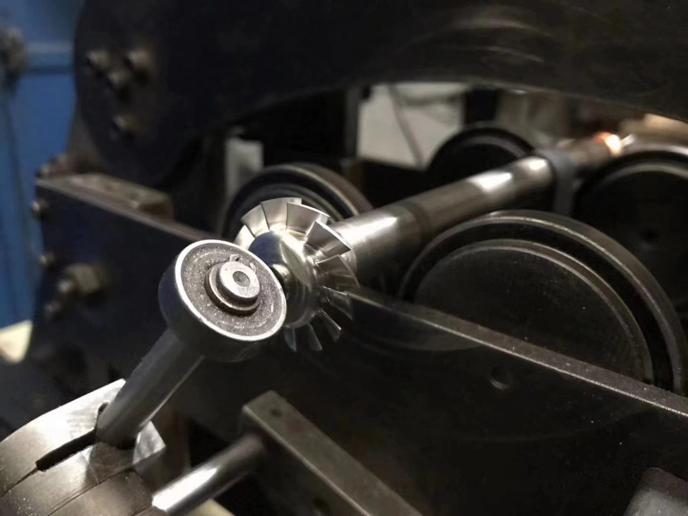
Impeller parts are generally processed using a five-axis CNC machining center. The advantage of five-axis machine tools is that they can process parts that cannot be processed by three-axis and four-axis machines, and avoid leaving dents on the blade surface . When the five-axis machine tool processes the impeller blades, the processing method is side cutting. Side milling can make the surface of the machined blade smooth.
During rough machining, the tool performs multi-layer machining on the impeller blade curved surface. After the material is removed in layers, the entire tool side edge is in contact with the blade curved surface during finishing, ensuring that the processed blade curved surface complies with the fluid mechanics characteristics.
Requirements for machine tools for impeller parts
The processing of integral impeller parts includes rough machining and finishing of the flow channel and rough machining and finishing of the blade curved surface. In terms of processing, four axes can be used to achieve rough machining and finishing of the flow channel. However, the rough machining and finishing of the blade surface must be achieved using a five-axis machine tool . Five-axis machine tools must have high positioning accuracy and repeatable positioning accuracy. The positioning accuracy is generally 0.0005MM/300MM. Generally, five-axis high-precision machine tools can meet the requirements.
There are many configurations of five-axis machine tools. Generally , the structure of three motion axes and two rotation axes is commonly used . Commonly used mechanisms for processing integral impellers are: (1) Tilt-rotary table vertical machine tool (2) Double rotary table horizontal machine tool (3) Tilt-rotary table machine tool (4) Spindle swing rotating gantry milling (5) Spindle Swing gantry milling machine with turntable.
Impeller parts manufacturing plan design
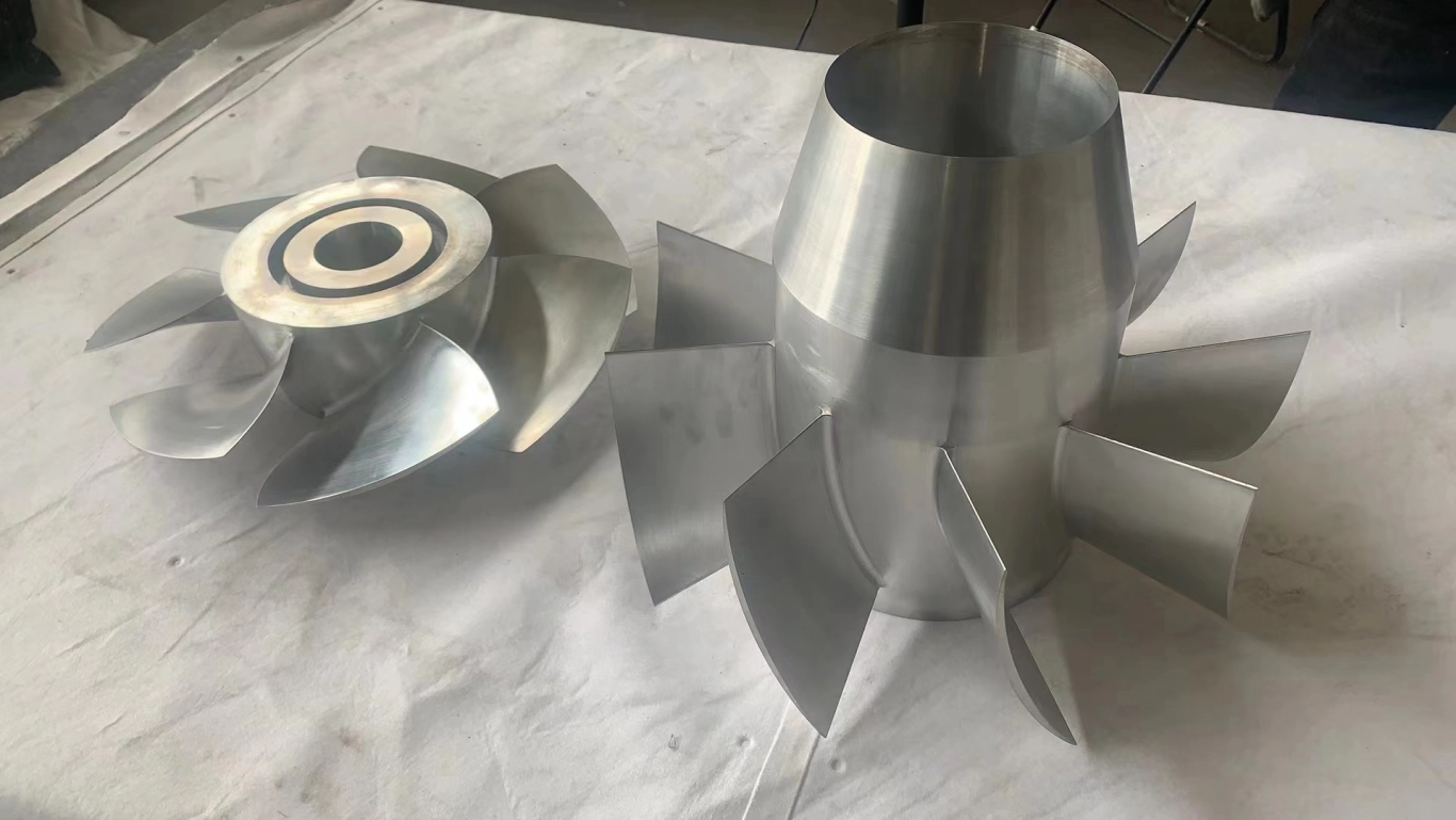
The impeller parts manufacturing plan uses five-axis linkage machining center machine tools. The multi-axis system function in the UGCAM software is used to perform layered rough milling on the flow channel surface and blade surface using variable axis cleaning . Then finish machining the bottom surface of the flow channel and the side blade surface of the impeller. The entire machining is separated from rough machining and finishing, and the cutting tools are also separated. The picture below is a physical picture of the impeller parts.
The picture below is a physical picture of the overall impeller parts. This integral impeller is the compressor rotor. It can be seen that the integral impeller has only one blade. There are 12 primary blades and 12 secondary blades. The blade height is relatively high, and the inlet height is 16MM . The height of the outlet blade is 3MM. The thinnest part of the blade is 0.8MM, and the minimum distance between adjacent blades is 4.8MM. This kind of integral impeller is difficult to process, mainly due to the deep flow channel groove, thin blades, and small blade spacing.
The overall impeller processing plan is: 1. CNC turning of the overall impeller hub shape 2. Rough machining of the impeller flow channel on a five-axis machine tool 3. Rough machining of the blade surface 4. Finishing path surface of the hub flow channel 5. Finishing of the blade side.
Additionally, there is a lot of material to remove between the blades. In order to make the impeller meet aerodynamic requirements, the blades often adopt a structure with a large twist angle and a round root, which places higher requirements on the processing of the impeller .
Automated programming process for impeller parts
As shown in the figure below, it is not the UG automatic programming process. As can be seen from the figure, the general steps of automatic programming are:
(1) Obtain the three-dimensional model of the part, analyze the three-dimensional part, determine its processing content, and select a processing machine tool based on the processing content . For different processing contents, machine tools must be reasonably arranged for processing. Processing content should be arranged in order. When processing, try to consider the economy and efficiency of processing. Only by placing parts suitable for machining center machine tools for processing can the advantages of CNC machine tools be fully utilized.
(2) Determine the installation position and clamping method, analyze and determine the installation direction of the part on the machine tool, determine the positioning datum , select the appropriate fixture, align the fixture and find the position of the workpiece coordinate system point.
(3) Arrange the processing content, conduct process analysis on the parts , and select different processing methods according to the different technical requirements of the processed parts.
(4) Process arrangement, the processing of parts should be divided into rough machining and finishing . The machining allowance for each process must be reasonably formulated and allocated.
The selection of process parameters and the process of processing parts include the formulation of cutting tools, cutting methods and cutting parameters .
The automatic programming process of impeller parts is the process of formulating the parts processing technology. After formulating the process, the automatically programmed processing program table must be filled in. The process table lists all parameter information of the processing process. Specifically, there should be the processing part of the part, the tool, the cutting amount (three elements), the cutting type, and the machining allowance.
After formulating the process list for automatic programming of the impeller, the automatic programming work needs to be completed one by one according to the process list . The specific content must be consistent with the process. This programming process is usually the job of a so-called NC programmer.
The above specifically analyzes the structure of the impeller parts, analyzes the processing technology of the impeller parts according to its structural characteristics, and points out the advantages and disadvantages of the impeller parts casting processing and five-axis linkage machining technology solutions. Finally, the manufacturing plan design of the impeller parts is given, and the processing technology content of the impeller parts is formulated.